A comprehensive reference guide to dust collection system components for metal fabrication, welding, and manufacturing applications. This guide covers the essential ductwork, control, and connection components you’ll encounter when designing, specifying, or maintaining industrial ventilation systems.
DUCTWORK COMPONENTS
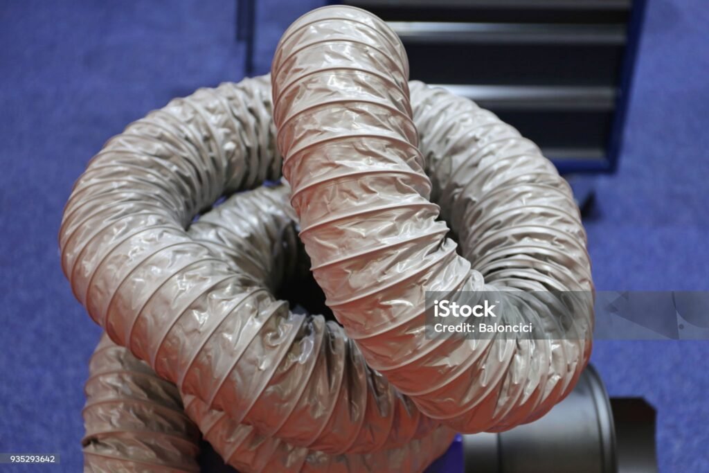
Flexible Hose
What It Is
Flexible hose (also called flex duct or flexible ducting) is corrugated or smooth-bore ducting that allows for movement and easy connection between fixed duct runs and equipment. Constructed from PVC, polyurethane, wire-reinforced materials, or metal with internal wire reinforcement to prevent collapse under vacuum.
How It Works
The corrugated or spiral-reinforced construction allows bending and flexing while maintaining structural integrity under negative pressure. Internal wire helix (typically bronze-coated spring steel or galvanized steel) prevents kinking and collapse when the duct is under suction.
When to Use
- Connecting movable equipment to fixed ductwork (portable grinders, welding fume arms)
- Absorbing vibration from dust collectors, fans, or machinery
- Navigating around obstacles where rigid duct is impractical
- Temporary installations or applications requiring frequent repositioning
- Short connection runs (typically less than 2-3 meters to minimize pressure drop)
- Applications where equipment moves or rotates during operation
Key Specifications
- Diameter: 40mm – 400mm (1.5″ – 16″) common range; larger sizes available
- Materials:
- PVC (light duty, economical, up to 70°C)
- Polyurethane (abrasion resistant, tear resistant, -40°C to +90°C)
- Neoprene-coated (spark resistant, oil resistant)
- Wire-reinforced metal flex (high temperature, up to 600°C)
- Wall thickness: 0.6mm – 1.5mm depending on application and material
- Bend radius: Minimum 1.5× diameter (tighter bends restrict airflow)
- Pressure rating: Typically -2,500 to -5,000 Pa (-10″ to -20″ WG)
Selection Criteria
- Abrasion resistance: Metal dust, sand, or wood chips require polyurethane or heavy-duty construction
- Static dissipation: Combustible dust applications (aluminum, wood, plastics) require static-dissipative or grounded hose per AS/NZS 60079 to prevent spark ignition
- Temperature: Match material rating to process temperature (welding fume may require silicone or metal flex)
- Chemical resistance: Corrosive fumes require neoprene, EPDM, or stainless steel construction
- Length: Minimize flexible hose length – pressure drop is approximately 3× higher than rigid duct of same diameter
Common Mistakes
- Using excessive length (every meter of flex hose creates ~3m equivalent of rigid duct pressure drop)
- Wrong material for abrasive dust (standard PVC tears quickly with metal grinding dust)
- Not grounding static-dissipative hose (defeats safety purpose, creates ignition risk)
- Crushing or kinking hose during installation (reduces effective diameter, increases system pressure)
- Using non-food-grade materials in food processing (material must meet FDA requirements)
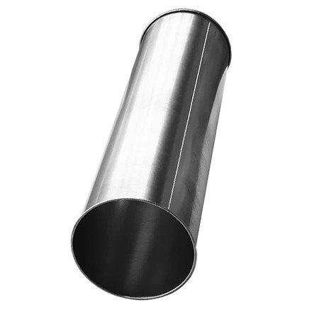
Straight Duct (Spiral & Galvanized)
What It Is
Straight duct pipe forms the main transport arteries of dust collection systems. Spiral duct is manufactured from continuous coiled metal strip formed into cylindrical pipe with an external spiral lockseam. Galvanized duct refers to steel duct with zinc coating for corrosion protection.
How It Works
Spiral lockseam construction creates a continuous reinforcing rib on the outside of the pipe, providing exceptional rigidity and strength. The four-ply metal spiral seam locks together mechanically, creating an airtight joint that runs the length of the pipe. This eliminates the need for longitudinal welding and provides superior structural strength compared to snap-lock or welded-seam duct.
When to Use
- Spiral duct: High-pressure systems (>1,500 Pa / 6″ WG), systems 3.5kW+ (5HP+), material conveying, long straight runs requiring fewer supports
- Standard galvanized: Lower pressure general ventilation, shorter runs, budget-conscious installations
- Main trunk lines in dust collection systems
- Applications requiring structural rigidity without external stiffeners
- High-velocity transport (>20 m/s / 4,000 ft/min)
Key Specifications
- Diameter: 75mm – 900mm (3″ – 36″) standard range; custom sizes to 1,500mm (60″)
- Gauge (thickness):
- 24 gauge (0.6mm) – Most common for dust collection
- 22 gauge (0.76mm) – Medium duty
- 20 gauge (0.91mm) – Heavy duty / high pressure
- 18 gauge (1.2mm) – Extra heavy duty
- Standard lengths: 1.5m (5 ft) and 3m (10 ft) sections
- Materials: G90 galvanized steel (most common), stainless steel 304/316, aluminum (food/pharma)
- Pressure rating: Withstands -5,000 Pa (-20″ WG) to -10,000 Pa (-40″ WG) depending on gauge
- Standards: SMACNA (Sheet Metal and Air Conditioning Contractors’ National Association), AS 4254 for dust collection
Selection Criteria
- System pressure: Higher vacuum requires heavier gauge (20ga for >-3,500 Pa / -14″ WG)
- Material transported: Abrasive materials (metal grindings) require 20-22 gauge minimum
- Span between supports: Spiral’s inherent strength allows 3-4m spans vs 1.5-2m for snap-lock
- Installation cost: Spiral costs 15-25% more than snap-lock but requires 40-50% fewer supports and 50% less installation time
- Corrosive environment: Stainless steel for chemical fumes, coastal/outdoor installations
Common Mistakes
- Undersizing duct diameter (increases velocity beyond material transport limits, causes abrasive wear)
- Using too thin gauge for system pressure (duct collapses inward under high vacuum)
- Forgetting to account for -2″ length when using couplers (actual 10 ft pipe is 118″ to allow for coupling overlap)
- Attempting to cut/crimp spiral duct with hand tools (requires motorized press; use slip-on adapters instead)
- Not specifying galvanized coating for outdoor installations (bare steel rusts rapidly)
- Spiral duct manufacturing meets SMACNA standards for industrial ventilation systems.
Elbows (45° and 90°)
What It Is
Elbows (also called bends) are curved fittings that change airflow direction in ductwork. The two most common angles are 45° (moderate direction change) and 90° (perpendicular direction change). Elbows are characterized by their radius: Long Radius (LR) = 1.5× diameter, Short Radius (SR) = 1.0× diameter.

How It Works
Elbows redirect airflow using smooth curved walls rather than sharp angles. The radius of curvature determines pressure drop: longer radius = gentler curve = lower turbulence = lower pressure loss. Most dust collection elbows are 5-piece construction (90°) or 3-piece construction (45°), with multiple gore sections welded together to form the curve.
When to Use
- 45° elbows: Moderate direction changes, lower pressure drop than 90° (typically 0.3-0.5 velocity heads vs 0.7-1.2 for 90°)
- 90° elbows: Perpendicular direction changes, turning vertical to horizontal or around obstacles
- Long radius: Preferred for dust collection to minimize turbulence and material dropout
- Navigating around building structure, equipment, or overhead obstructions
- Transitioning between vertical and horizontal duct runs
Key Specifications
- Diameter: 75mm – 600mm (3″ – 24″) standard; larger available
- Angles: 15°, 30°, 45°, 60°, 90° (90° and 45° most common)
- Radius:
- Long Radius (LR): 1.5× diameter centerline radius (recommended for dust collection)
- Short Radius (SR): 1.0× diameter centerline radius (use only when space-constrained)
- Construction:
- Small diameters (75-150mm / 3-6″): Press-formed halves, stitch-welded seam
- Large diameters (200mm+ / 8″+): Segmented (gored) construction with 5 gores for 90°, 3 gores for 45°
- Materials: Galvanized steel, stainless steel 304/316, carbon steel
Selection Criteria
- Pressure drop: Use 45° elbows when possible (50-60% lower pressure drop than 90°)
- Space constraints: Short radius saves space but increases pressure drop by 40-60%
- Material settling: Long radius reduces particle dropout in horizontal-to-vertical transitions
- Abrasive wear: Position weld seams away from high-impact zones; consider abrasion-resistant liners for metal dust
- Installation: Two 45° elbows often better than one 90° for material flow and pressure optimization
Common Mistakes
- Using short radius elbows unnecessarily (dramatically increases system pressure drop)
- Positioning elbows too close together (creates turbulence, material accumulation)
- Installing 90° elbow immediately after hood (causes separation, poor capture)
- Not accounting for directional airflow in tubed elbows (collar orientation matters – inside collar for inlet, outside for outlet)
- Placing elbows in vertical legs where material can settle and plug (use 45° offsets instead where possible)
CONTROL COMPONENTS
Blast Gates
What It Is
Blast gates (also called dampers or shut-off gates) are manually or automatically operated slides that control airflow through ductwork by opening or closing a port. The gate consists of a cast aluminum or steel body with a sliding blade (galvanized steel or stainless steel) that moves across the duct opening.

How It Works
A sliding blade moves perpendicular to airflow, either fully opening the duct passage (gate open) or completely blocking it (gate closed). Manual gates use a handle on the exterior; automatic gates use compressed air cylinders (pneumatic actuation) controlled by solenoid valves that open/close based on machine operation signals.
When to Use
- Isolating individual machines or workstations in multi-pickup dust collection systems
- Energy savings: close gates at idle machines to prevent unnecessary airflow
- Balancing system airflow by throttling specific branches
- Emergency shut-off for maintenance or troubleshooting
- Automatic gates: Connecting to machine power supply – gate opens only when machine operates (saves 40-60% energy vs continuously running all branches)
Key Specifications
- Diameter: 75mm – 750mm (3″ – 30″) standard range
- Body material:
- Cast aluminum (lightweight, standard duty, 75-200mm / 3-8″)
- 10-12 gauge galvanized or stainless steel (heavy duty, 200-600mm / 8-24″)
- Blade material: Galvanized steel or stainless steel (12-14 gauge)
- Actuation:
- Manual: Handle-operated with locking pin
- Automatic: Pneumatic cylinder (requires minimum 75 psi compressed air, 120V solenoid standard)
- Seal: Special low-friction sealing device reduces air leakage when closed
Selection Criteria
- Manual vs automatic: Automatic saves energy but requires compressed air and electrical control
- Frequency of operation: Manual suitable for infrequent adjustments; automatic for machines cycling on/off throughout day
- Dust type: Abrasive materials require heavy-gauge steel body (cast aluminum wears quickly)
- Pressure rating: Ensure gate rated for system vacuum (standard gates suitable to -5,000 Pa / -20″ WG)
- Installation position: Gates should be accessible for operation and maintenance
Common Mistakes
- Installing blast gates on dirty-air side of collector (dust accumulates in gate body, prevents sealing)
- Using gates for airflow balancing instead of proper system design (gates create excessive pressure drop when throttled)
- Not grounding metal gates in combustible dust systems (static electricity ignition risk)
- Positioning automatic gate too far from machine (dust escapes before gate closes)
- Forgetting to specify reed switches for automated systems requiring gate position feedback
Dampers
What It Is
Dampers are adjustable airflow control devices similar to blast gates but typically used for continuous throttling rather than on/off control. The term “damper” and “blast gate” are sometimes used interchangeably, but dampers often refer to butterfly-style or multi-blade designs for proportional airflow control.
How It Works
Dampers restrict airflow by partially blocking the duct cross-section. Butterfly dampers use a rotating disc; volume control dampers use multiple opposed blades. The degree of opening determines airflow volume – partially closed increases resistance and reduces CFM through that branch.
When to Use
- Fine-tuning system balance across multiple branches
- Maintaining consistent transport velocity when dust loading varies
- Seasonal adjustments (winter vs summer airflow requirements)
- Test and balance procedures during commissioning
- Backdraft dampers: preventing reverse airflow when fan stops
Key Specifications
- Types:
- Butterfly damper: Single rotating blade, simple, low cost
- Multi-blade damper: Multiple opposed blades, better throttling control
- Backdraft damper: Gravity-operated, prevents reverse flow
- Diameter: 75mm – 600mm (3″ – 24″) typical
- Materials: Galvanized steel, stainless steel, or aluminum
- Operation: Manual (with locking quadrant) or motorized actuator
Selection Criteria
- Control precision: Multi-blade dampers provide finer airflow adjustment than butterfly type
- Pressure drop: Dampers add resistance; use only when necessary for balancing
- Backdraft prevention: Use backdraft dampers on system discharge to prevent contaminated air from re-entering system when fan stops
- Position indication: Graduated quadrant shows damper angle for repeatability
Common Mistakes
- Over-reliance on dampers for balancing instead of proper duct sizing
- Installing damper in wrong orientation (blade axis should match airflow for lowest pressure drop)
- No locking mechanism (dampers vibrate open/closed during operation)
- Using dampers as primary shutoff device (blast gates are better for full closure)
Diverter Valves
What It Is
Diverter valves redirect airflow from one duct path to another using a rotating or sliding gate mechanism. Unlike blast gates that shut off flow, diverter valves maintain continuous airflow while changing its direction – typically splitting one inlet into two outlets at 45° or 90° angles.

How It Works
A pivoting blade inside a Y- or T-shaped housing rotates to direct airflow to outlet A or outlet B. Manual diverter valves use external handle; automatic valves use pneumatic cylinders with solenoid control. The blade position determines which outlet receives airflow while blocking the alternate path. Heavy-duty flange bearings and rubber seals ensure smooth rotation and minimal leakage.
When to Use
- Routing material from single source to multiple destinations (one grinder feeding two dust collectors)
- Directing airflow between two dust collectors (primary unit and backup/overflow)
- Process control: sending product-grade material to one location, off-spec to another
- Alternating between filtration stages or collection bins
- Automatic operation: Systems where diversion must occur based on process conditions, container full signals, or automated production sequences
Key Specifications
- Diameter: 75mm – 600mm (3″ – 24″) standard
- Angle: 45° most common (lower pressure drop), 90° for space-constrained installations
- Body material:
- 14 gauge black steel (economy)
- 3/16″ (4.8mm) heavy welded steel plate (standard duty)
- 304 or 316 stainless steel (corrosive environment / food grade)
- Actuation:
- Manual: External handle with detent positions
- Automatic: Double-acting pneumatic cylinder (75 psi minimum), 120V solenoid (other voltages available)
- Construction: Heavy-duty flange bearings for smooth rotation, rubber seal in door/blade
Selection Criteria
- Manual vs automatic: Automatic required for real-time process control; manual sufficient for infrequent changeovers
- Material abrasiveness: Abrasive materials (metal grindings) require heavy-plate construction and replaceable wear liners
- Frequency of operation: High-cycle applications need heavy-duty bearings and seals
- Control integration: Automatic valves require compressed air system and PLC/control integration
- Optional reed switch: Provides valve position feedback to control system
Common Mistakes
- Undersizing valve inlet/outlets (creates bottleneck, increases pressure drop significantly)
- Not accounting for material buildup on inactive outlet side (can jam valve on next operation)
- Inadequate compressed air pressure for automatic actuation (below 75 psi causes slow/incomplete actuation)
- Positioning valve too far from collection point (material settles in horizontal runs)
- Forgetting to specify correct voltage for solenoid (120V standard; 240V, 24V available)
CONNECTION COMPONENTS
Quick-Disconnect Clamps
What It Is
Quick-disconnect clamps (QF clamps, Quick-Fit clamps, or snap clamps) are specialized band clamps that connect modular ductwork sections without bolts, screws, rivets, or welding. The clamp consists of a galvanized or stainless steel band with integral handle, a bridge pin that locks the clamp closed, and a rubber seal (nitrile, silicone, or ePTFE gasket) that creates an airtight joint.

How It Works
Duct sections have rolled ends (QF ends) that create a lip. The clamp slides over the two rolled ends and is tightened with a single lever motion. The bridge pin engages to lock the clamp closed. The rubber seal compressed between the two rolled lips creates an airtight, leak-tight connection without fasteners. Installation takes seconds; disassembly is equally fast – no tools required.
When to Use
- Modular dust collection systems requiring frequent reconfiguration (job shops, facilities with changing layout)
- Applications needing easy disassembly for cleaning (food processing, pharmaceutical)
- Installations where welding is prohibited (explosive atmosphere classifications)
- Temporary or portable dust collection setups
- Reducing installation labor (45-50% faster than flanged ductwork)
- Systems requiring frequent maintenance access
Key Specifications
- Diameter: 75mm – 600mm (3″ – 24″) standard
- Materials:
- Galvanized steel band (standard, most applications)
- 304 stainless steel (food/pharma, corrosive environments)
- Seal materials:
- Nitrile (standard, -40°C to +120°C, suitable for oil mist)
- Silicone (high temp, -55°C to +200°C)
- ePTFE (chemical resistance, FDA approved, -200°C to +260°C)
- Components: Steel band, bridge pin (locking mechanism), gasket seal
- Leakage rate: Third-party tested to <0.5% (significantly better than bolted flanges)
Selection Criteria
- Temperature: Silicone seals required above 120°C; ePTFE for extreme temperatures
- Chemical exposure: ePTFE seals resist all common industrial chemicals
- Food-grade requirements: ePTFE seals + stainless steel clamps for FDA compliance
- Frequency of disconnection: QF systems excel where maintenance/cleaning access is frequent
- Cost vs labor: QF systems cost 10-15% more in materials but save 40-50% in installation labor
Common Mistakes
- Mixing clamp materials with duct materials (galvanized clamp on stainless duct creates galvanic corrosion)
- Using standard nitrile seals in high-temperature applications (seal degrades, system leaks)
- Not specifying ePTFE seals for chemical service (nitrile/silicone degrade with chemical exposure)
- Insufficient rolled-end depth on custom fittings (prevents proper clamp engagement)
- Attempting to use QF clamps on non-QF ductwork (requires hose adapters or transition pieces)
Flanges
What It Is
Flanges are rigid metal rings (flat plates or angle iron) attached to duct ends that allow two sections to be bolted together. Flanges create strong, permanent or semi-permanent connections using bolt-and-gasket assemblies. Common types include angle ring flanges (L-shaped steel angle), flat flanges, and Van Stone flanges (formed lip on duct with slip-on backing ring).

How It Works
Flanges are attached to each duct section by welding, riveting, or screwing. Gasket material (neoprene, EPDM, or cork) is placed between the two facing flanges. Bolts passing through holes in both flanges are tightened, compressing the gasket to create an airtight seal. Properly installed flanged connections withstand high positive or negative pressure.
When to Use
- Permanent installations not requiring frequent disassembly
- Heavy-duty applications with high pressure (>7,500 Pa / 30″ WG)
- Large diameter ductwork (>600mm / 24″)
- Connecting ductwork to fans, dust collectors, or other equipment
- Structural applications requiring rigid, load-bearing connections
- Code-required applications (grease ducts, fire-rated barriers)
Key Specifications
- Types:
- Angle ring: L-shaped steel angle (typical 50×50mm / 2″×2″), welded or riveted to duct
- Flat flange: Flat plate welded to duct (very rigid, heavy-duty)
- Van Stone: Formed lip on duct with separate slip-on backing ring (labor-saving)
- Materials: Mild steel (galvanized or painted), stainless steel 304/316
- Bolt holes: Pre-drilled, typically 10mm (3/8″) diameter on standard bolt circle
- Bolt spacing: 100-150mm (4-6″) on center for standard pressure; 75mm (3″) for high pressure
- Gasket material: 3-6mm (1/8″ – 1/4″) thick neoprene, EPDM, or cork
Selection Criteria
- Pressure rating: Angle rings suitable to -7,500 Pa (-30″ WG); heavier flanges for higher pressures
- Diameter: Angle rings economical for <600mm; flat flanges common for larger sizes
- Installation permanence: Flanges for permanent; quick-disconnect clamps for semi-permanent
- Material compatibility: Stainless flanges for stainless duct; galvanized for galvanized
- Gasket selection: Temperature and chemical compatibility must match application
Common Mistakes
- Under-tightening bolts (leakage) or over-tightening (crushes gasket, causes leaks)
- Not aligning flanges before tightening (creates gaps, prevents proper sealing)
- Using mis-matched bolt materials (use stainless bolts with stainless flanges; galvanized with galvanized)
- No gasket or damaged gasket (major source of system leakage)
- Bolt hole misalignment (requires field drilling, weakens flange)
- Nuts not on same side (poor practice, interferes with insulation/jacketing)
- Properly installed flanged connections withstand high positive or negative pressure per ASHRAE guidelines.
HOOD COMPONENTS
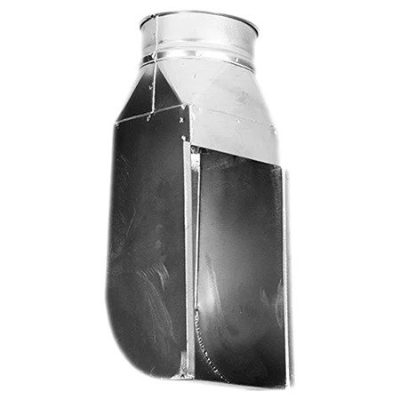
Capture Hoods
What It Is
Capture hoods are the interface between the dust collection system and the dust-generating process. Hoods are designed to create airflow patterns that capture contaminant-laden air at the source and convey it into the ductwork. Hood types include enclosing hoods (fully or partially surround the source) and capturing hoods (positioned near but not surrounding the source).

How It Works
Hoods work by generating controlled airflow with sufficient velocity to overcome opposing air currents and capture particulate or fume at its generation point. The hood creates a capture zone where air velocity must equal or exceed the capture velocity (typically 0.5-2.5 m/s / 100-500 ft/min depending on contaminant). Proper hood design considers source characteristics, hood type, hood position, and required airflow (CFM).
When to Use
- Enclosing hoods: Preferred whenever possible – surrounds process to contain dust (grinding enclosures, downdraft tables)
- Canopy hoods: Rising hot contaminants (welding fume, hot processes) – hood positioned overhead
- Side-draft / backdraft hoods: Large or immovable workpieces – hood behind workpiece, draws air across work surface
- Slotted hoods: Long, narrow sources (open tanks, bench edges) – elongated slot creates uniform suction
- Bell mouth / exterior hoods: Open pickup where enclosure impossible – provides lowest entry loss but requires highest CFM
Key Specifications
- Hood types:
- Canopy hood: Rectangular or round overhead hood for rising contaminants
- Backdraft hood: Vertical rear exhaust plenum, open front for workpiece access
- Downdraft table: Perforated work surface over exhaust plenum (grinding, welding, deburring)
- Slotted hood: Elongated slot (typically 5-10cm / 2-4″ wide) along length of tank or bench
- Bell mouth: Flared funnel-shaped entry (increases capture efficiency, reduces entry loss)
- Materials: Galvanized steel, stainless steel 304/316, aluminum (spark-sensitive applications)
- Design basis: Most hoods designed for 0.75-1.5 m/s (150-300 ft/min) capture velocity at specified distance
Selection Criteria
- Enclosure first: Always prefer enclosing hood over capturing hood when possible (requires 50-90% less airflow)
- Contaminant characteristics: Rising fume → canopy; heavy dust → downdraft; mist → backdraft
- Position: Hood must be located between contaminant source and operator’s breathing zone
- Accessibility: Hood must not interfere with work or material handling
- Flanges/baffles: Adding flanges around hood opening increases capture efficiency 25-50%
- Distance: Every doubling of distance from source to hood requires 4× CFM; keep hood as close as possible
Common Mistakes
- Positioning hood too far from source (CFM requirement increases with square of distance)
- Hood placed where operator stands between contaminant and hood (draws dust through breathing zone)
- Undersized hood opening (increases required face velocity, creates noise and turbulence)
- No flanges on exterior hoods (flanges dramatically improve capture, reduce CFM requirements)
- Ignoring cross-drafts from windows, doors, fans (can overwhelm hood capture velocity)
- Specifying fixed hoods for variable processes (movable hoods or articulated arms more effective)
- Proper hood design considers source characteristics, hood type, hood position, and required airflow (CFM). For detailed hood design calculations, refer to the ACGIH Industrial Ventilation Manual.
Conclusion
Understanding the function, specifications, and selection criteria for dust collection equipment components is essential for designing effective industrial ventilation systems. Each component plays a specific role:
- Ductwork components (flexible hose, straight duct, elbows) transport contaminated air with minimum pressure drop and maximum reliability
- Control components (blast gates, dampers, diverter valves) enable system balancing, energy savings, and process integration
- Connection components (quick-disconnect clamps, flanges) provide leak-tight joints appropriate to installation requirements
- Hood components capture contaminant at the source, the most critical aspect of system performance
Proper component selection based on material characteristics, system pressure, temperature, and application requirements ensures optimal performance, energy efficiency, and long equipment life. When in doubt, consult dust collection system professionals or refer to ACGIH Industrial Ventilation Manual and SMACNA standards for detailed design guidance.
END OF EQUIPMENT GUIDE